Skip to content
Automation simplifies one of metal fabricating's most challenging cutting applications
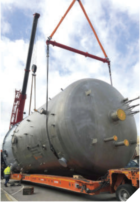
Ask any fabricator about the toughest part of building a pressure vessel or storage tank, and you’ll likely get the same answer: the dome, or head. Whether dished, torispherical, or conical, each dome must be fitted with precisely located openings, bevels, and trims that align seamlessly with adjoining shells.
For decades, dome cutting remained as much art as science. Intersections were physically laid out using templates and projection drawings. Intersection points were calculated, marked on curved surfaces, and manually cut with plasma or oxyfuel torches. The process was slow, inconsistent, and highly dependent on the skill of experienced craftsmen.
Today’s fabricators face rising demands for precision, speed, and repeatability while contending with a shrinking pool of experienced operators. At the same time, domes have grown larger and tolerances tighter. Traditional manual cutting methods are not only reaching their practical limits in terms of accuracy and efficiency, but they also pose serious safety and health risks. Operators often must work from scaffolding to reach upper surfaces, surrounded by hot sparks, heavy dust, and metal fumes—conditions that increase both physical strain and exposure hazards. Together, these challenges underscore the need for a safer, more automated approach to dome cutting.
Over the last decade, advanced fabricating technology has emerged to help with this challenging fabricating task. What has really made a difference is the use of complete dome-body scanning, a breakthrough that transformed dome cutting from a manual, high-risk task into a precise, largely automated workflow.
Why Dome Cutting Is Challenging
Fundamentally, cutting a dome is vastly different from cutting plate. While flat surface cutting involves two linear axes (and a height-sensing Z axis), a dome is a continuously curving surface, with every point having its own tangent and normal vector. Because of this, maintaining correct bevel angles and torch standoff requires the cutting head to continually adjust orientation in multiple axes. Even the smallest deviations in tilt or offset can skew bevel profiles, misalign penetrations, or distort edges.
Compounding this difficulty, the actual geometry of a formed dome rarely matches its theoretical CAD model. Variations in pressing, forming, weld distortion, or material springback may shift radius or depth across the surface. Such deviations, even in millimeters, can corrupt intersection layouts.
Traditionally, fabricators compensated via measurement, hand-marking, and trigonometric calculation. While that approach can, in many cases, deliver acceptable results, it is difficult to standardize, replicate, or scale to larger-diameter domes.
Scanning and Automation
These dome cutting challenges have been overcome through a combination of advanced automation, precision control, and integrated scanning technology. The process begins with the preparation of the CNC cutting program in a 3D-processing environment. An operator can import a 3D STEP model of the desired dome, complete with hole penetrations, marking lines, and even fitted nozzles. The CAM software recognizes the dome shape and the required cut paths, from simple single-pass contours to complex weld preparations such as Y, X, or K bevels. A fully defined CNC program can be created in a matter of minutes.
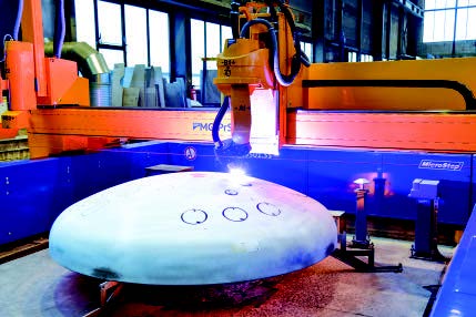
Once the program is ready, this advanced system proceeds to the scanning phase. A linear laser scanner is used to capture the actual dome surface in full detail, establishing the foundation for true as-built cutting. The scan captures the true geometry, which leads to the creation of a toolpath that is perfectly aligned and accurate, even when the dome isn’t perfectly round.
During scanning, the cutting machinery’s control system synchronizes scanner data with all machine motion axes, applying corrections based on measured kinematics and calibration data for both the scanner and the bevel head. This generates a precise point-cloud model of the dome relative to the machine coordinate system. What’s more, the entire scanning process is noncontact, as the machine never physically touches the dome surface.
Next, a calibration tool measures and compensates for tool offsets, wear, and angular misalignment, ensuring that the torch orientation, tilt, and rotation precisely match the as-scanned geometry in all axes. The control system then automatically compares the ideal CAD model with the scanned dome surface and adjusts the cutting toolpaths accordingly. Because cutting relies solely on the scanned results, manual height probing or touch-based measurement before cutting is not required.
The cutting phase itself is fully automated as the torch follows programmed paths across the dome while dynamically maintaining bevel angle, standoff distance, and local tangency. Unlike legacy systems, the same setup can handle hole penetrations on the crown, bevel cuts on the knuckle, and trimming of the bottom edge, all in a single, continuous operation.
At the end of the cutting process, operators receive an automatically generated measurement report, which can be archived for production tracking or included as part of a quality assurance plan for critical applications.
This dome cutting technology is not limited to small workpieces. While many tank and vessel fabricators routinely cut domes up to 20 ft. in diameter, this type of automated dome cutting technology can accommodate much larger domes. Ongoing projects include machines designed to cut dome petals, individual dome segments measuring up to 55 ft. across. The cutting equipment’s modular design also enables the combination of dome, flat, and pipe cutting capabilities within a single machine envelope.
The Operator's Role
So how does this automation affect the operator? Instead of measuring, laying out lines, or guiding cuts manually, operators now manage a digital workflow.
The operator’s job becomes less about detailed craftsmanship and more about process control. Training focuses on safe setup, scan validation, calibration routines, and toolpath verification.
An operator who understands scanning and calibration can achieve accuracy that was once possible only for those with extensive experience.
Best Practices for Repeatable Accuracy
While automation handles much of the precision, consistent results still depend on disciplined process control:
Surface preparation – Remove soot, scale, or spatter before scanning to avoid missing data or glare.
Scan verification – Review the 3D point cloud in the CAM software and confirm coverage across knuckles, weld seams, and transition areas.
Routine calibration – Run the calibration program at shift start or after torch maintenance.
Geometry revalidation – Scan again after welding or heat treatment.
Standardized file management – Use consistent naming and workflow conventions.
In an industry historically reliant on experienced craftsmanship, dome cutting has finally evolved. This process that once required manual calculations and tribal expertise has been transformed into an automated and data-driven operation delivering consistent quality, higher throughput, and measurable return on investment.